Simplifed HowTo Guide, mostly for private networks at home. Enterprises
might/should use enterprise wireless security settings, enterprise wifi site
survey etc. Please Note: As always: No guarantee; Always backup your existing config before changing
anything; Harden your setup (see below);
1. Intro
Howto expand your WiFi with two different wireless radios.
Example:
|Original AP| -------- 2.4Ghz Chan 1 SSID1 -------- |MikroTik AP|-------- 5 Ghz Chan 36 SSID1 --------
SSID1 extended with MikroTik AP on another band & channel
|Original AP| -------- 2.4Ghz Chan 1 SSID1 -------- |MikroTik AP|-------- 5 Ghz Chan 36 SSID1 --------
SSID1 extended with MikroTik AP on another band & channel
2. HowTo Guide with MikroTik
HowTo Guide with MikroTik hAP2 (dual radio access point) in RouterOS
v6.42.6 (stable)
You should have:
You should have:
- Your MikroTik dual radio access point available, powered on, have access to it
- Think about doing a firmware update to the latest stable firmware
- Backup your existing RouterOS cfg
- Information about your wifi you want to extend (SSID name, Pre-Shared-Key (PSK), on which band and channel it is broadcasted)
2.1. Connect to existing wireless network with radio1
2.1.1. Access GUI & Login
2.1.2. Select Wireless -> Security Profiles -> Add new:
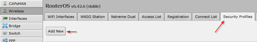
2.1.3. SecurityProfile-Name
- Enter a SecurityProfile-Name, for example: SecProf-yourSSIDname
- Select the authentication type of your existing wifi
- Enter the Pre-Shared-Key (PSK) of your existing wifi:

2.1.4. Wireless -> Scanner

2.1.5. Select wlan1 as interface and press start

2.1.6. Select your wireless signal which you want to extend

2.1.7. Press connect

2.1.8. Wireless\WiFi interfaces -> Select wlan1

2.1.9. Setup the first radio as „wireless client“
- Set mode to „station pseudobridge“
- Set band to the band of your existing wifi
- Set frequency to the channel of your existing wifi or use auto
- Use the security profile you created in step 2.1.2. and 2.1.3. with the correct psk:

Press apply. The status should change to „connected to ess":

2.2. Extend your existing wireless network with radio2
2.2.1 Wireless\WiFi Interfaces -> Select wlan2

2.2.2. Setup the second radio as „wireless access point“
- Set mode to „ap bridge“
- Set band to the band of the extended wifi signal
- Set frequency to the channel for the extended wifi signal (if possible a free channel)
- Use the same SSID name as your existing wifi
- Use the security profile you created in step 2. and 3. with the correct psk
- Set bridge mode to enabled

2.3. Connect both radios with each other using a bridge
2.3.1. Bridge\Bridge -> Add new

2.3.2. Enter a name for the bridge, for example WLAN-Bridge01:

Confirm with OK
2.3.3. Assign both wireless interfaces to bridge:
Bridge\Ports -> Select wlan1:

2.3.4. Set Bridge to your created Bridge (from step 13, for example WLAN-Bridge01):

2.3.5. Assign second wireless interfaces to bridge:
Bridge\Ports -> Select wlan2:
2.3.6. Set Bridge to your created Bridge (from step 13, for example WLAN-Bridge01):

2.3.7. Safe your MikroTik configuration
2.3.8. Test to connect to your extened WiFi
3. General WiFi-Tips
- Do a wireless site survey (perfect heatmap with non-overlapping channels and keep it updated after wifi is alive and changes)
- Use 20Mhz channels when there is a lot of noise in the air
- Use strong wireless security (wpa2-enterprise or long wpa2-psks with aes-ccm)
- Check for rogue access points (e.g. with access points with 3 radios)
- Harden your MikroTik
- Keep your wifi solutions up to date
- Turn of old wireless standards as tkip, wep, wpa1, 802.11b
- Use band steering & disconnected clients at a low signal strength to force them to roam


